|
Implementation
Of
Modulation
Techniques
on SpinCore PulseBlasterDDS
and RadioProcessor Boards
Introduction
SpinCore's
PulseBlasterDDS and RadioProcessor boards can be used to perform a
variety of signal modulation techniques. Signal modulation allows for
one signal to be transmitted using another signal. This procedure is
useful because some signals cannot physically be transferred over
certain media. The original signal is referred to as the
modulating signal, and the signal that it is packed inside of is
referred to as the carrier. Signal modulation is used for everyday
applications such as FM & AM radio, ethernet communications, and
HDTV.
These
pages show how to implement a wide variety of signal modulation
techniques on PulseBlasterDDS and RadioProcessor boards. They also show
the
use of these boards to generate carriers of various shapes that could
be
used in NMR experiments.
A simple
block diagram of the SpinCore
PulseBlasterDDS-I-300 board is given in Figure 1. The
PulseBlasterDDS-I-300 board consists of two major
building
blocks. Both of the blocks are controlled by the same master clock.
1. DDS
Core
This block mainly consists of
a numerically controlled
oscillator (NCO), an arbitrary waveform generator (AWG) and an
attenuator. It also contains frequency, phase and amplitude
registers that hold the parameters that are used by the NCO, AWG and
the attenuator.
2. PulseBlaster Timing
Core
This block controls the
registers in the DDS core and
is used for generating TTL outputs for triggering RF signals on the
oscilloscope in this work.
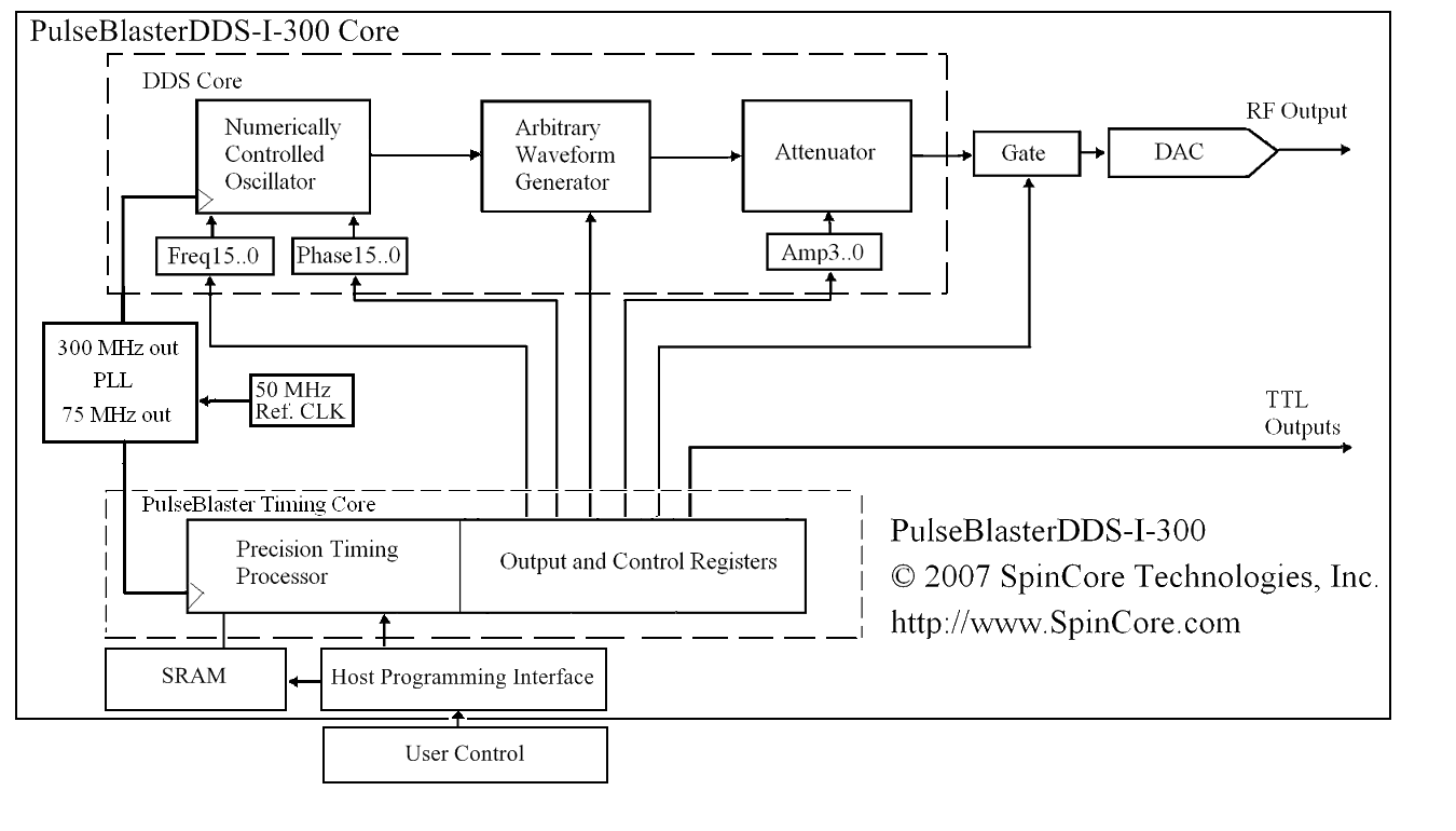
Figure
1:
PulseBlasterDDS
Architecture.
The
complete
C
code demonstrating the techniques described below will be provided with
the next version of SpinAPI, but for now can be found here.
The modulation techniques
are further explained in the sections given
below.
Modulation Techniques:
1. Analog
Modulation
Figure
2:
Analog
modulation
refers
to
the
process
of
transferring
an
analog
baseband
(low
frequency)
signal,
like an audio
or TV signal, over a higher frequency signal such as a radio frequency
band.
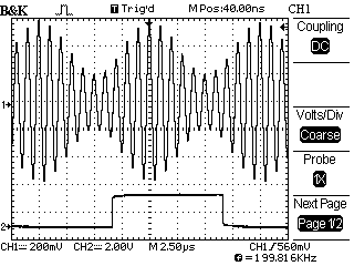
Figure
2 shows an AM waveform on the first channel and the TTL output on the
second channel of a dual-channel oscillocope. Here, the carrier
frequency Fc was set to be equal to 1 MHz and a sine wave message
signal having a frequency Fm=100 kHz was used with a modulation index
of 50%.
Details about an implementation on the SpinCore PulseBlasterDDS board
is given here.
2. Digital
Modulation
Figure 3: Digital
modulation
is used to
transfer a digital bit stream over an analog channel at a high
frequency.
This enables us to transmit signals generated in a digital circuit
across a physical medium. This is because digital signals can be
handled with higher security and precision.
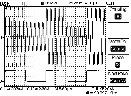
Figure
3
shows
a
type
of
digital
modulation
technique
known
as
Amplitude
Shift
Keying
(ASK)
for
a carrier frequency of Fc=500 KHz and a digital bit
rate = 100KHz for the baseband signal. The digital signal had an
amplitude of 0.5Vp-p for a logic 0 and 1.0 Vp-p for a logic 1. In
the
figure, the first channel shows the result of ASK and the second
channel shows the original digital signal.
Details
about
an implementation on the SpinCore PulseBlasterDDS board is given here.
3. Pulse
Modulation

Figure
4:
Pulse
modulation
methods
are
used
to
transfer
narrowband
analog
signals
such
as
voice signals over a wideband channel or, in some
schemes, as a bit
stream over another digital transmission system.
Figure
4
shows
output
pulse
amplitude
modulated
result
on
the
first
channel
and
the
TTL
outputs
on
the second channel for a carrier frequency of Fc=1 MHz and a
sine wave message signal with a frequency of
Fm=100 kHz.
Details
about
an
implementation
on
the
SpinCore
PulseBlasterDDS
board
is
given here.
|


 Contact Us | Software Downloads