The PulseBlaster MATLAB GUI provides a
simple but powerful user interface for
SpinCore Technologies, Inc. PulseBlaster™.
It allows the user to control the
PulseBlaster board, and create complex pulse
sequences without ever writing a single line
of code.
-
Provides
access to the full instruction set
available to the PulseBlaster™.
-
Allows easy
to change TTL signals without knowledge
of hexadecimal or knowledge of
board specifications.
-
Can take
advantage of multiple PulseBlaster™
boards simultaneously.
-
Compatible
with most SpinCore hardware devices,
which are TTL pulse generation capable.
This software has only been tested with
the PulseBlaster™ (SP17 and SP2) boards.
-
NOTE: This
software is unsupported and is provided
"AS IS" with no warranty, express or
implied.
Download and
Installation
Please verify that you have SpinAPI installed
on your computer prior to installing the
PulseBlaster MATLAB GUI. SpinAPI can be found
at
SpinAPI: SpinCore API and Driver Suite.
Next download the
PulseBlaster™ MATLAB GUI .zip file. Next,
unzip the downloaded file and place its
contents into the MATLAB directory you plan on
working in. Next, open MATLAB and navigate
into the PulseBlasterGUI directory that was
downloaded. Then in your MATLAB command prompt
type '
PulseBlasterGUI'.
The PulseBlasterGUI window will open.
Downloads
PulseBlaster MATLAB GUI (01-11-2017) .zip file
(64-bit)
Download Link
PulseBlaster24 Example Code
Download Link
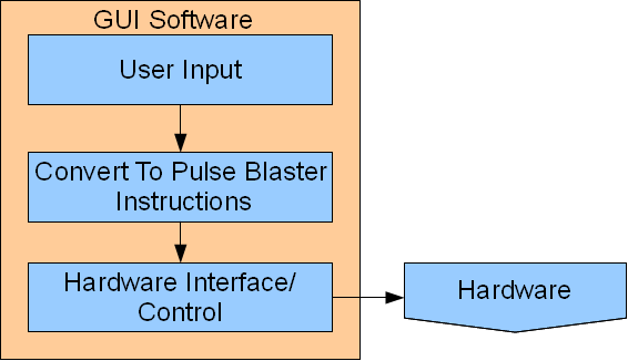
Program Flow
The PulseBlaster GUI begins the process by
acquiring the instructions input by the
user. Then these instructions are loaded
onto the PulseBlaster™ board, and the
program begins when the user presses start.
This causes the PulseBlaster™ hardware to
begin executing the users instructions and
outputting pulses on the TTL lines.
 User Interface
The main window
is the only window which is used in the
PulseBlaster™ MATLAB GUI. It contains a
variety of controls which allow the user to
create instructions, change parameters, and
perform specific functions. They are
categorized into the following groups:
Menu Bar
The menu bar allows the user to run
traditional program functions such as
saving. It has the following menu items:
- File
- New File
- Opens a new PulseBlaster™
instruction set. It will ask you if
you would like to save the current
instruction set.
- Open File
- Opens a file navigator to
open existing PulseBlaster™
instruction set. It will ask you if
you would like to save the current
instruction set.
- Save
- Will save your current
PulseBlaster™ instruction set. If you
have not previously saved this
instruction set it will open a file
navigator to ask you where to save your
instruction set.
- Save As
- Will open a file navigator
to ask you where to save your current
instruction set.
- Exit
- Will exit the GUI and ask you if you
would like to save the current
instruction set.
- Help
- Manual...
- Will bring you to the SpinCore web
page.
- About...-
Will open a dialog box that provides
information about the current version of
PulseBlaster MATLAB GUI you are using.
Information Box
-
SpinAPI Version - Will tell you
what SpinAPI version you are using. It
will show an error message if a version
SpinAPI is not found.
- Board
Number - An editable text box
that allows you to type in what SpinCore
board you would like to control. Boards
count in decimal from the number 0
upwards. Will return "no board found" if a
board is not detected.
-
Firmware ID - will output the
firmware of the current SpinCore board
that is selected.
Instruction Box
- Duration
Box - Specifies how much time
each instruction will take.
-
Editable text box - that allows
you to enter a decimal number specifying
how many time periods as specified by
the units drop down menu that each
instruction will take.
- Drop
down menu - allows you to
select the unit of time that the
editable text box will be scaled by. It
has the selectable values of nanosecond
(ns), microsecond (us), millisecond
(ms), second (s), minute (min), and hour
(hr).
- Output
State Box - Specifies what TTL
lines should be high or low for each
instruction
-
Check Boxes - Allows you to
make a TTL line logic high for that
instruction cycle by selecting the check
box with a left click of the mouse.
- Text
box - allows you to enter a
hexadecimal representation of the logic
levels of the TTL lines for each
instruction. Should not be preceded by
0x or any other hexadecimal specifier.
Should only include ascii 0-F.
- Flow
Control Box - Allows you to
control what instruction to go to next
- Drop
down menu (Flow Control) -
allows you to select the available
PulseBlaster™ instructions. They are
seen in the table below.
- Edit
text box (Flow Control Data) -
allows you to enter Instruction data
from each instruction that changes
attributes of certain instructions.
These attributes can be seen the table
below under Flow Control_data.
|
Flow Control
|
Flow Control_data
|
Function
|
|
CONTINUE
|
Ignored
|
Program
execution continues to next
instruction
|
|
STOP
|
Ignored
|
Stop
execution of program (*Note:
Output behavior is dependent
on device firmware. All TTL
outputs will either hold the
value assigned from the
previous instruction or reset
to zero. All analog outputs
will turn off)
|
|
LOOP
|
Number of desired loops. This
value must be greater than or
equal to 1.
|
Specify beginning of a loop.
Execution continues to next
instruction. Data used to
specify number of loops
|
|
END_LOOP
|
Address of beginning of loop
|
Specify end of a loop.
Execution returns to beginning
of loop and decrements loop
counter.
|
|
JSR
|
Address of first subroutine
instruction
|
Program execution jumps to
beginning of a subroutine
|
|
RTS
|
Ignored
|
Program execution returns to
instruction after JSR was
called
|
|
BRANCH
|
Address of next instruction
|
Program execution continues at
specified instruction
|
|
LONG_DELAY
|
Number of desired loops. This
value must be greater than or
equal to 3.
|
For
long interval instructions.
Data field specifies a
multiplier of the delay field.
Execution continues to next
instruction
|
|
WAIT
|
Ignored
|
Program execution stops and
waits for software or hardware
trigger. Execution continues
to next instruction after
receipt of trigger. The
latency is equal to the delay
value entered in the WAIT
instruction line plus a fixed
delay of 6 clock cycles. A
WAIT instruction must be
preceded by an instruction
lasting longer than the
minimum instruction time.
|
Pushbuttons
- Load
Board - Loads the current
instruction set as specified in the
instruction list box onto the currently
selected PulseBlaster™.
- Start
- Will send the start command to the
currently selected PulseBlaster™. This
will make the PulseBlaster™ begin to
output pulses.
- Stop
- Will send the stop command to the
currently selected PulseBlaster™. This
will stop the current instruction
execution.
- Add
Instruction Below - Will create a
new instruction below the currently
selected instruction in the Instruction
List box.
- Remove
Instruction - Will remove the
currently selected instruction in the
Instruction List box.
Instruction
List Box
The Instruction List Box provides a
view of the current instructions and all of
their parameters in the order that they will
be loaded into the PulseBlaster™ hardware.
They will be executed from first instruction
to last instruction, with the exception of
program flow instructions branch, loop, jump
to subroutine that will modify the program
execution order.