|
Implementation
of Pulse Amplitude Modulation on PulseBlasterDDS
and RadioProcessor Boards
Introduction:
Pulse modulation
methods are used to transfer a narrowband analog
signal, such as a phone call, over a pulse
stream. Some schemes use a digital signal for
transmission, making them essentially an
analog-to-digital conversion.
Three main variants
of Pulse Modulation are:
1. Pulse-amplitude
modulation (PAM).
2. Pulse-width modulation (PWM).
3. Pulse-position modulation (PPM).
Pulse Amplitude
Modulation (PAM) is the simplest of all Pulse
Modulation Techniques. In PAM, the amplitude of
the message or modulating signal is mapped to a
series of pulses, with two possible variant
detailed below:
Flat Top PAM:
The amplitude of
each pulse is directly proportional to the
instantaneous modulating signal amplitude at the
time of pulse occurrence and then keeps the same
amplitude of the pulse for the rest of the half
cycle.
Natural PAM:
The amplitude of
each pulse is directly proportional to the
instantaneous modulating signal amplitude at the
time of pulse occurrence and then follows the
amplitude of the modulating signal for the rest
of the half cycle.
PAM has
applications in ethernet communication and in
LED drivers, among others.
Natural
PAM implementation on SpinCore PulseBlaster DDS
Boards.
For generation of a
PAM waveform on PBDDS Board, the carrier
waveform is generated using the NCO. The AWG is
used to generate a waveform to modulate the
carrier signal.
The generation of
the modulating waveform in C code is shown
below:
void
shape_make_sin(float *shape_data)
{
int i;
for(i=0; i <
1024; i++)
{
shape_data[i]
=(sin(2.0*pi*((float)i/1024.0)));
}
}
The carrier waveform
is a series of square pulses with amplitude of
1V.
It can be generated
in the C code as follows:
void
shape_make_carrier(float *dds_data)
{
int i,j;
for
(i=0;i<samples;i++)
{
if (i<(samples/2))
dds_data[i] = 1.0;
else
dds_data[i] =0.0;
}
}
Both the above generated signals are loaded into
the board by using the SpinAPI function as given
below:
pb_dds_load
(shape_data, DEVICE_SHAPE);
pb_dds_load (dds_data, DEVICE_DDS);
The complete C code demonstrating this
implementation is available for direct
download.
In the source code, the message signal defaults
to being a sine wave. However, any waveform can
be used for the message signal, as shown below.
Note: Tm=1/Fm can not be less than (9 * clock
period) for the board to function properly (Tm =
modulating signal time period).
Example of PAM output generated on a SpinCore
PulseBlasterDDS board are shown in the figures
below.
|
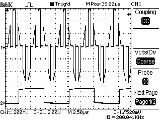
Figure 1
shows a PAM waveform generated using the
example source code on a PulseBlasterDDS
board.
Channel 1
shows the output PAM wave for carrier
frequency Fc = 1 MHz and modulating
signal frequency Fm = 100 kHz. The
modulating signal used is a sine wave.
Channel 2
shows the TTL output with frequency =
Fm/2.
Each cycle
of the TTL output corresponds to the
time taken to execute the two SpinAPI
functions given below:
pb_inst_radio_shape(0,0,0,0,
TX_ENABLE,
NO_PHASE_RESET, NO_TRIGGER,
USE_SHAPE, 0, 0x0F,CONTINUE, 0,
tm*us);
pb_inst_radio_shape(0,0,0,0,
TX_ENABLE, NO_PHASE_RESET,
NO_TRIGGER, USE_SHAPE, 0,
0x00,BRANCH, start, (tm)*us);
The
execution of these instructions results
in the generation of two full cycles of
the PAM signal.
Also note
that Channel 1 output is delayed by (9 *
clock cycle) time period.
|
|
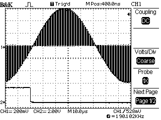
Figure 2
shows output PAM waveform generated
using the example source code but with
different parameters.
In this example, the carrier frequency
is set to Fc = 1 MHz and the modulating
frequency is set to Fm = 200 kHz.
|
|
Figure 3
shows output PAM waveform generated
using the same example code but this
time with modulating frequency of Fm =
10 kHz. The carrier frequency remains
unchanged.
|
|
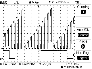
Figure 4 shows the output PAM waveform
generated using the example source code,
but this time the modulating signal used
is a ramp waveform instead of a sine
signal. The modulating frequency
is set to Fm = 100 kHz and the carrier
frequency remains Fc = 1 MHz.
|
These are only the
basics of what can be done using SpinCore's
PulseBlasterDDS and RadioProcessor boards.
Please see the example code in SpinAPI and the
product manuals for more details.
|